LUSAS 활용
활용사례 및 기타 자료
Understanding and utilizing axisymmetric elements
LUSAS 활용
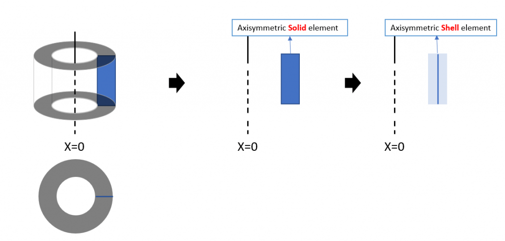
Axisymmetric elements are used to easily proceed with analysis by modeling only one section instead of modeling the entire structure with axisymmetric behavior.

1. Axisymmetric load
Since axisymmetric behavior is assumed, all loads and boundary conditions are also assumed to be axisymmetric. Load conditions for structures can only be defined in the central direction (X) and vertical direction (Y).
For example, the internal pressure shown on the left is defined as the load applied to the line in the two-dimensional axisymmetric model as shown on the right.

If the above load is applied, the deflection will be expressed as below.

The central direction (SX) has compressive stress (- sign), and the circumferential direction (SZ) has tensile stress (+ sign) as the ring is forced to expand.

2. Axisymmetric boundary conditions
Since axisymmetric behavior is assumed, all loads and boundary conditions are also assumed to be axisymmetric. Boundary conditions for structures can only be defined for the central direction (X) and vertical direction (Y).
Constraining the X direction on the model (middle picture below) means setting constraints in the center direction.

Vertical direction boundary conditions can also be specified as needed using the same concept.
Since the circumferential direction is one section of a continuous structure, there cannot be a separate boundary condition, and resistance is proportional to the elastic modulus of the material.
The central stress (SX) has a compressive stress (- sign), and the circumferential stress (SZ) has a compressive stress (- sign) because it receives internal pressure while the outside of the structure is restrained.

3. Resulting stress direction
As in the previous example, loads or boundary conditions on the model can only be applied in the central direction (X) and vertical direction (Y), but stresses can also be checked in the circumferential direction (SZ).
4. Interaction by boundary conditions with adjacent structures
Interaction with adjacent structures can be expressed using Joint elements.

By specifying the spring constant for each direction in the material property of the joint element, the connection characteristics with adjacent structures are defined. Direct boundary conditions for the axisymmetric structure specify only X (center direction) and Y (vertical direction), and only the circumferential direction is specified. While resistance is proportional to the elastic modulus of the material, the boundary condition with the adjacent structure must be expressed as a spring without a material model for the circumferential direction, so the condition for C (circumferential) must also be specified.

For reference, due to the nature of an axisymmetric structure, if the central direction ku is specified, the effect of being constrained in the circumferential direction occurs even if the circumferential direction kc is not specified. In an axisymmetric structure, the radius and circumferential length are proportional, so just as there is no displacement in the circumferential direction if there is no displacement in the central direction, when constraints are set in the central direction, the circumferential direction is also constrained.
By changing the type of spring material properties, nonlinear springs such as compression/tensile resistance, contact, and bilinear can be applied.

(1) Translational displacement in the center direction
Set the ku value by placing the specified joint element.

You can specify the spring constant per unit area by matching Line to Line.

(2) Vertical translational displacement
Set the kv value by placing the specified joint element.

(3) Circumferential translational displacement
Set the Kc value by placing the specified joint element.

5. Interaction through connection with adjacent structures
If the adjacent structure does not use the same two-dimensional axisymmetric element, but uses a shell or beam element, and shear connectors, etc. are used to connect the adjacent structure, transmission of rotational displacement may be necessary.

(1) Use of axisymmetric shell elements
Axisymmetric solid models (2D Axisymmetric solid elements) only have translational displacements, so they cannot express moment transfer. You can also consider using Shell elements for the structure to be analyzed.

The rotational displacement transmitted through THz corresponds to the rotational displacement caused by a moment in the vertical direction, as shown in the figure below.

Since the structure, load, and boundary conditions all assume axis symmetry, rotational displacement in the circumferential direction or in-plane rotation as shown in the figure below does not occur.
If it is necessary to consider such rotational displacement, a 3D model must be used since the load/deflection, etc., is not axisymmetric.

(2) Mixture of axisymmetric solid + axisymmetric shell
As the analysis model of this structure must perform (thermal analysis + structural analysis) simultaneously, if it is necessary to model the thickness, a method of implementing only the connecting member (e.g. shear connecting member) using the Axisymmetric Shell element is used. You can also think about doing it.

Typically, the connecting material is not an axisymmetric structure with continuity in the circumferential direction, but it is simulated as an Axisymmetric Shell element with continuity in the circumferential direction, and instead of using the original cross-sectional dimensions or elastic modulus, the strength of the original connecting material in each direction is axisymmetric. Even in the modeled state, the equivalent thickness/elasticity coefficient must be converted and applied to achieve the same level.

Analysis by construction stage is a nonlinear analysis that performs analysis in the form of adding a structure or adding a load in the next stage, using the deflection and stress state of the previous stage as the initial conditions.

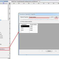
Among the pop-up menus linked to material data, Temperature Dependence… Select to specify the temperature and the material properties at that temperature.

Axisymmetric elements are used to easily proceed with analysis by modeling only one section instead of modeling the entire structure with axisymmetric behavior. We summarize contents related to loads, boundary conditions, and result extraction in structural analysis using axisymmetric elements.
