
LUSAS provides an environment that can perform various analyzes within the same model file. When constructing a 3D static analysis model, by selecting one of the four construction stage scenarios, the settings required for the analysis are defined, and it is completed by defining only the size of the load...
Wind load calculation and application
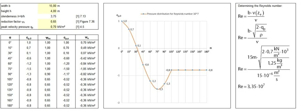
The wall wind load is Peak Velocity Pressure, qp(z), External Pressure Coefficient (Cpo), End Effect Factor, Ψλα. It is determined by three factors: the wind load pressure at a specific height z is qp(z) * Cpo * Ψλα.
Base-Wall, Wall-Roof connection details
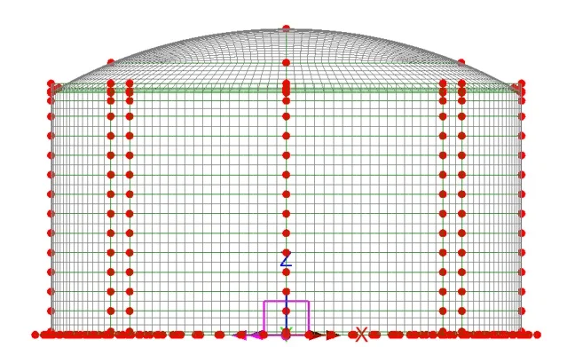
At the connection between the roof and ring beam, and the wall and base slab, dummy elements constructed to compensate for the gaps that occur when constructing the model based on the center line are defined as shown in the figure below.
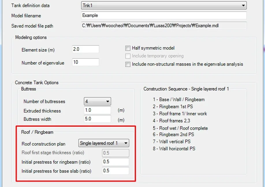
2D model construction stage classification details
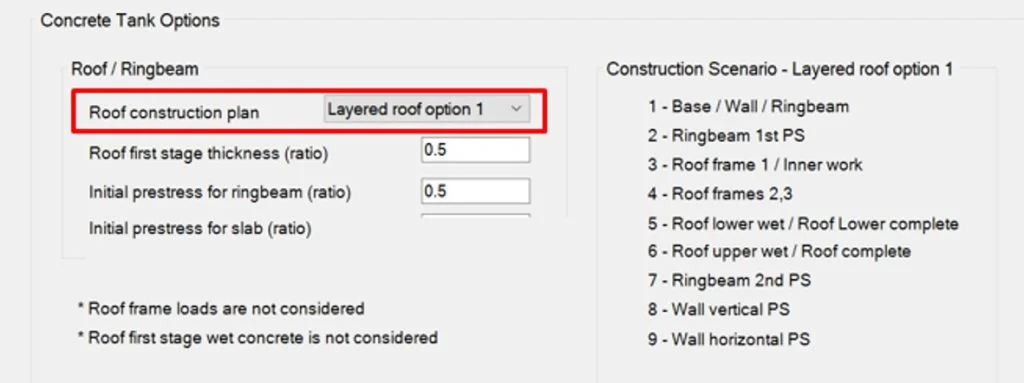
LNG Tank > Create 2D model > Staged Construction… In the menu, each construction stage is defined differently depending on the roof construction plan.
Enter insulation material specifications
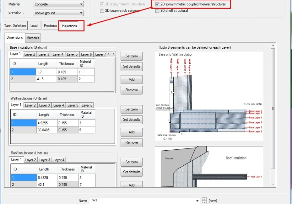
Base Insulation Up to 6 insulation layers can be defined. Wall Insulation Up to 4 insulation layers can be defined. It is assumed that roof insulation is constructed from the inner upper surface of the last wall insulation.
Update from Support (3D)
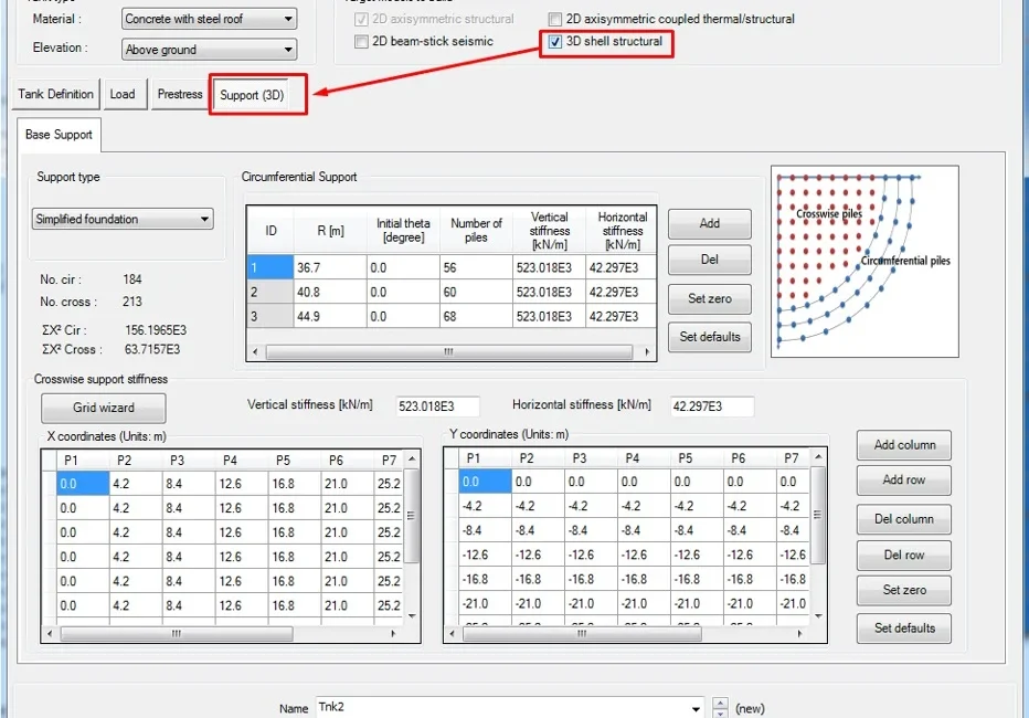
If you select the '3D shell structural' option among 'Target models to build', you can define additional information required when creating a 3D shell model, and the 'Support(3D)' tab is also added as shown below.
Wall Stages
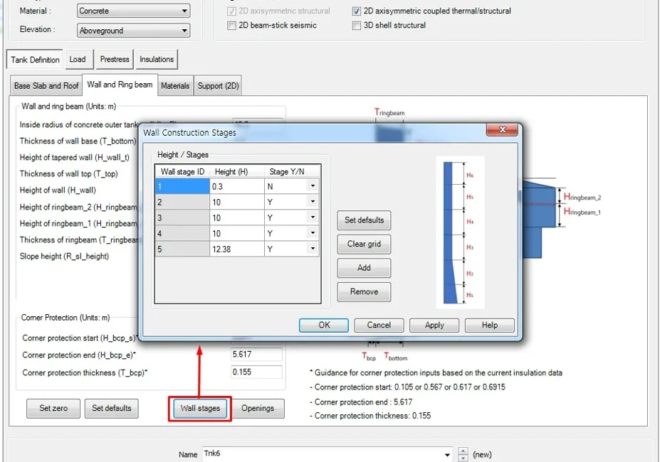
If you want to consider changes in cross-sectional force at each construction stage for a wall, click the Wall Stage button to specify it. In this case, this example shows how the construction stage is defined according to the Stage (Y/N) setting.